Mechanics: State, evaluate and apply mechanical advantage
Unit 3: Gears and mechanical advantage
Leigh Kleynhans
Unit outcomes
By the end of this unit you will be able to:
- Define gears and gear trains.
- Distinguish between the use of gears and pulleys.
What you should know
Before you start this unit, make sure you can:
- Identify, describe, and apply principles of simple machines and mechanical advantage. See level 2 subject outcome 2.4 to revise this.
- Define torque. See level 4 subject outcome 2.4, unit 1 to revise this.
Introduction[1]
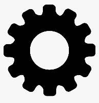
In this section you will see how gears can be used in a simple machine. A is a rotating machine part with one or more wheels with teeth usually made of metal or plastic. These wheels are called .
Gears are all around us and are found in just about everything that has spinning parts. For example, car engines, wind-up toys, non-digital clocks, drills, bicycles, car transmissions, powered wheelchairs, and lifts. Gears are used in machines to:
- change direction of rotation
- change speed of rotation
- change torque (force).
How do gears work?
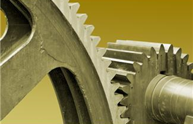
Gears are arranged with two cogs that have their locked into each other. The teeth in each cog are the same size. Since the teeth fit together, when one cog is turned, it causes the other cog to turn as well. If the first cog is rotated clockwise, the direction of the rotation of the other cog will be anti-clockwise (and vice versa). In this way gears can be used to change the direction of rotation.
When two cogs of different diameters are connected in a gear, slow rotation of the large cog will cause the smaller cog to rotate quickly. The gear in this case can increase the input speed of rotation to a higher output speed.
Turning a large cog slowly requires less energy than it would to rotate the small one quickly. By using cogs, there is saving of energy, making work easier. In this way, gears can change the torque and create mechanical advantage.
If cogs are different diameters, they will have different numbers of teeth. The ratio of the number of teeth in two meshed cogs is referred to as the . For example, if one gear has [latex]\scriptsize 60[/latex] teeth and another has [latex]\scriptsize 20[/latex], the gear ratio when these two gears are connected together is [latex]\scriptsize \displaystyle 3:1[/latex] The smaller cog will complete three rotations for every one rotation of the bigger cog.
Note
Watch the following video which explains the basics of gears.
Why are gears needed?
Some of the machines used in our daily life would be impossible to operate without gears. A car is a perfect example. The combustion and electrical engines that power cars use suitable gear systems to regulate engine power. For example, in a car transmission system, the driver (or an automated transmission mechanism) selects the appropriate gear ratio depending on the power required. On a flat road, a high gear ratio allows the vehicle to speed up, while when climbing up a hill, a small gear ratio produces the necessary (torque) force to move the vehicle up the slope.
Gear trains
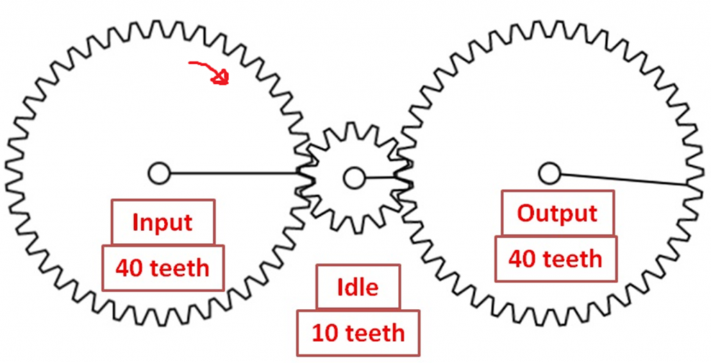
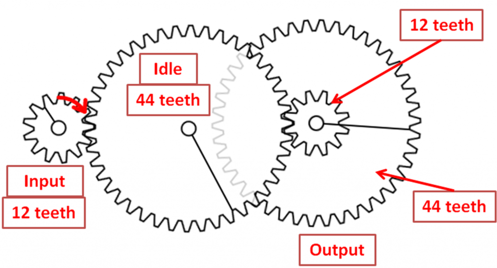
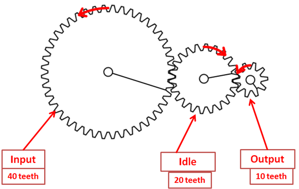
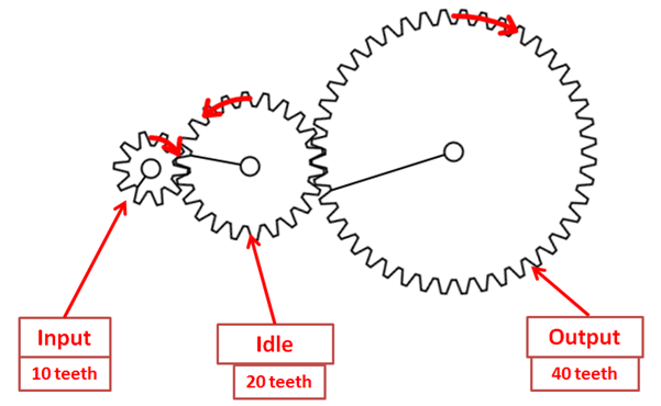
Multiple gears are often connected together in gear trains, as illustrated in figure 3. When gears in a are the same size, they rotate at the same speed and transfer the same torque or force. However, when the gears are different sizes either more torque/force or more speed will result.
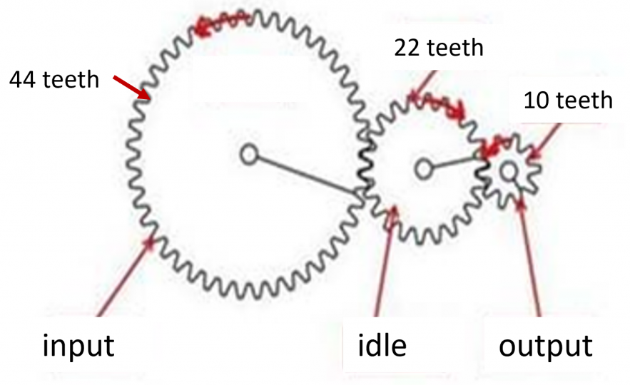
When we have two or more gears meshed together, the gear attached to the motor is called the and the gear attached to the wheel is called the . Any cogs between the input and the output are referred to as . The idle gear can ensure that the output and the input gear rotate in the same direction.
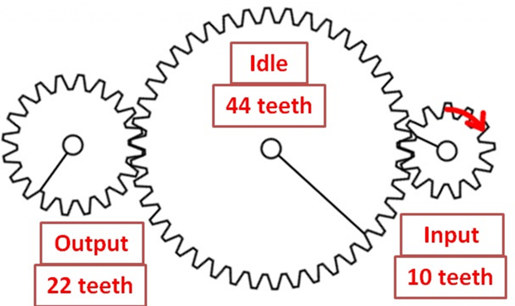
The gear ratio will be the ratio of the number of teeth on the output gear versus the number of teeth on the input gear (the drive gear). For the gear train in figure 3, the gear ratio will be [latex]\scriptsize 44\text{ : 10 or 22 : 5}[/latex].
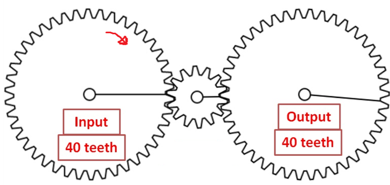
When the input gear is larger than the output gear, the output gear rotates faster; this is called gearing up. The output gear provides less torque but moves at a higher speed. For example, many bicycles have different gears. When you would like the bike to go faster, you can change to a higher gear, so that it can provide speed, though it will do so with less force. When the input gear is smaller than the output gear, the output will rotate slower; this is called gearing down. Though it rotates slower, the torque from the output gear is more. In the example of a bicycle, when you want to climb a hill, you can change to a lower gear to get more force, though at a slower speed.
The difference between gears and pulleys
Now that you have studied both gears and pulleys, you can identify the similarities and differences between these two types of simple machines. Pulleys are mainly used to lift large, heavy objects providing a mechanical advantage so that less force is required. Gears are mainly used to increase speed of rotation with less torque.
However, pulleys can also be arranged to provide the same advantage as gears. The wheel of one pulley is driven by a motor and a belt is looped around this wheel and around a second wheel. When the motor is turned on, the powered wheel turns the belt which turns the second wheel.
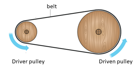
If the two pulleys have different diameters, there will be a difference in the rotational speed. A pulley allows you to have more distance between the wheel axles, but they transmit less torque compared to gears, as they can allow slip to happen when the tension force exceeds the friction. With gears there is no slip, but the gear teeth need to be in contact with each other. Gear systems require a much more precise alignment than pulley systems.
Summary
In this unit you have learnt the following:
- A gear is a rotating machine part with cut teeth that mesh with another toothed part in order to transmit torque, increase speed or change direction of rotation.
- A gear train is a system of multiple gears.
- The gear ratio is the number of teeth on the input gear to the number of teeth on the output gear.
- Pulleys can be arranged to perform a similar function to gears.
Unit 3: Assessment
Suggested time to complete: 15 minutes
- Define the following terms:
- gear
- gear train
- gear ratio
- How is a gear ratio designed for a particular application?
- Give the gear ratios illustrated below and state the direction of rotation of the output gear:
- .
- .
- .
- .
- In the gear assembly diagrams below, which one:
-
- produces torque?
- produces speed?
- is neutral?
-
| A | B | C |
 |
 |
 |
- For each of the following situations, say whether you would use a pulley system, a gear system or either:
- raising a flag
- in a motorised garage door
- lowering a heavy load onto the deck of a ship
- rotating the drum of a washing machine
The full solutions are at the end of the unit.
Unit 3: Solutions
Unit 3: Assessment
- .
- a rotating machine part with cut teeth that mesh with another toothed part in order to transmit torque
- two or more gears connected together
- the ratio of the number of teeth on the input gear to the number of teeth on the output gear
- Some applications (machines) may need to be fast, while other machines may need to be strong. When designing gears for a machine, it is important to know whether speed or torque (strength) is more important. In general, if you need to have more torque, select a large gear ratio. If you need to move fast, then use a smaller gear ratio.
- .
- [latex]\scriptsize 1:1[/latex] clockwise
- [latex]\scriptsize 11:5[/latex] clockwise
- [latex]\scriptsize 1:1[/latex] clockwise
- .
- B – output gear has larger diameter than input gear
- A – output gear has smaller diameter than input gear
- C – output and input gears are the same size
- .
- pulley
- either
- pulley
- either
Media Attributions
- img01_Figure1 © Jeffrey Laut, Paul Phamduy is licensed under a CC BY (Attribution) license
- img02_Figure2 © Jeffrey Laut, Paul Phamduy is licensed under a CC BY (Attribution) license
- img03_Figure3 © Jeffrey Laut, Paul Phamduy is licensed under a CC BY (Attribution) license
- img04_Figure4 © Jeffrey Laut, Paul Phamduy is licensed under a CC BY (Attribution) license
- img05_AssessmentQ3 © Jeffrey Laut, Paul Phamduy is licensed under a CC BY (Attribution) license
- img05_AssessmentQ3 © Jeffrey Laut, Paul Phamduy is licensed under a CC BY (Attribution) license
- img05_AssessmentQ3 © Jeffrey Laut, Paul Phamduy is licensed under a CC BY (Attribution) license
- img06_AssessmentQ4 © Jeffrey Laut, Paul Phamduy is licensed under a CC BY (Attribution) license
- img06_AssessmentQ4 © Jeffrey Laut, Paul Phamduy is licensed under a CC BY (Attribution) license
- img06_AssessmentQ4 © Jeffrey Laut, Paul Phamduy is licensed under a CC BY (Attribution) license
- Parts of the text in this unit were sourced from Teach Engineering released under a CC-BY licence. ↵
a rotating machine part with cut teeth that mesh with another toothed part in order to transmit torque
wheels with teeth
the pointed edges around the perimeter of a cog
the ratio of the number of teeth on the input gear to the number of teeth on the output gear
two or more gears connected together
the gear attached to the motor, also called the drive gear
the gear attached to the wheel, also called the follower gear
the gears between the input and the output gears
