Electricity and electronics: State and apply principles and components used in electronics
Unit 3: Digital electronics
Leigh Kleynhans
Unit 3 outcomes
By the end of this unit you will be able to:
- Identify basic principles of digital electronics – logical gates.
- Identify symbols and use of active circuit elements and identify components from circuit diagrams, namely:
- LEDs
- diodes
- transistors
- operational amplifiers.
What you should know
Before you start this unit, make sure you can:
- Describe the principles of a p-n junction in diodes. Refer to level 4 subject outcome 4.2 unit 2 if you need help with this.
Introduction
Circuits often do not only consist of a power source, conducting wires, resistors, capacitors, and inductors. In this unit you will be introduced to further circuit components, specifically those used in electronic or digital circuits.
What are logic gates?
Logic gates are the building blocks of . They are basically used to perform logical operations by acting as a switch between options. A logic gate is an electronic device that creates logical decisions depending on the various combinations of digital signals accessible on its inputs (sensors). A digital logic gate can have more than one input signal but has only one digital output signal.
A logic gate accepts the input and operates on a required condition. If a certain condition is true, it turns ‘ON’ (also referred to as HIGH) and goes ‘OFF’ (also referred to as LOW) when the condition is false.
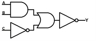
The functioning of a logic gate is expressed using what is referred to as a truth table. It displays all possible combinations of the inputs and a column against each row shows the corresponding output value. Figure 1 shows an example of logic gate circuit which has three inputs A, B, C, and single output Y.
Types of logic gates
There are seven types of logic gates. They are:
- NOT gate (inverter)
- AND gate (multiplication)
- OR gate (addition)
- NAND gate
- NOR gate
- XOR gate
- XNOR gate.
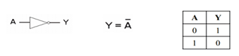
NOT gates (inverter)
The output of a NOT gate is ‘high’ if the input is ‘low’ and vice versa.
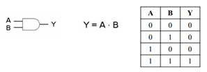
AND gates (multiplication)
The output of an AND gate is ‘high’ if both the inputs are high, and the output is ‘low’ if both or either of the inputs is ‘low’.
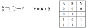
OR gates (addition)
The output of an OR gate is ‘high’ if both the inputs are ‘high’ or one of the inputs is ‘high’. The output is ‘low’ if both the inputs are ‘low’.
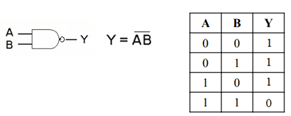
NAND gates
The output of a NAND gate is ‘high’ if both the inputs are ‘low’ and if either of the inputs is ‘low’. The output is ‘low’ if both the inputs are ‘high’.
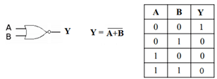
NOR gates
The output of a NOR gate is ‘high’ if both the inputs are ‘low’. The output is ‘low’ if both the inputs are ‘high’ or either of the inputs is ‘high’.
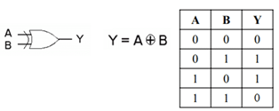
XOR gates
The output of a XOR gate is ‘high’ if either of the inputs is ‘high’. The output is ‘low’ if both the inputs are ‘high’ or if both the inputs are ‘low’.
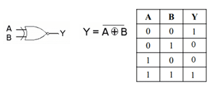
XNOR gates
The output of a XNOR gate is ‘high’ if both the inputs are ‘high’ or if both the inputs are ‘low’. The output is ‘low’ if either of the input is ‘low’.
The working principle of logic gates
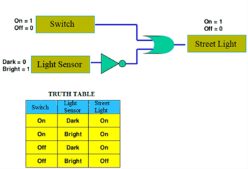
To understand the working principle of logic gates, let us consider the example of a street lighting system. Figure 9 shows the circuit diagram of a street lighting system which consists of logic gates (a NOT gate and an OR gate), a switch and a light sensor. The operational condition for the streetlights to function is as follows:
Switch: On = 1, Off = 0
Light sensor: Dark = 0, Bright = 1
Streetlight: On = 1, Off = 0
Based on this, we can prepare a truth table as shown in figure 9:
Applications of logic gates
There are a number of applications of logic gates.
- They are used in circuits involving computation and processing.
- They are also used in push button switches, e.g. a door bell.
- They are used in the functioning of streetlights.
- AND gates are used to enable/inhibit data transfer.
- NAND gates are used in burglar alarms and buzzers.
Exercise 3.1
- What are logic gates?
- How many different logic gates are there? List them.
- Give three examples of where logic gates are used.
The full solutions are at the end of the unit.
Active circuit elements
The components you have been learning about so far — resistors, capacitors, and inductors — are called passive components. They do not change their behaviour and therefore always have the same response to changes in voltage or current. Active components are quite different. They respond to changes in input, and this allows them to be used as circuit components called diodes, transistors, and amplifiers, which are used in calculators and computers.
Diodes
A diode is an electronic device that allows current to flow in one direction only.
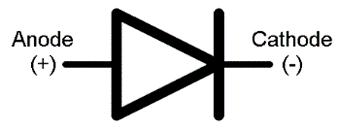
A diode consists of two doped semiconductors joined together so that the resistance is low when connected one way and very high the other way.
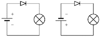
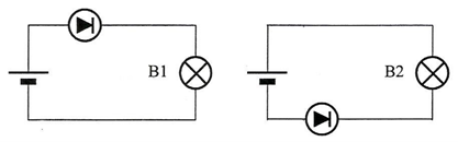
Look at the circuit diagrams in figure 11. In the circuit diagram on the left, the diode is forward biased, and current is permitted. The negative terminal of the battery is connected to the negative terminal of the diode. In the circuit diagram on the right, the diode is reverse biased and current flow is not allowed. The negative terminal of the battery is connected to the positive terminal of the diode.
Diodes are used for:
- power conversion – to convert power to power.
- demodulation of signals – to remove the negative component of an AC signal.
- over-voltage protections – protection devices for sensitive electronic components.
- current steering – to make sure current only flows in the proper direction.
The light-emitting diode (LED)
A light-emitting diode (LED) is a diode device that emits light when charge flows in the correct direction through it.

The colour depends on the semiconducting material used to construct the LED, and can be in the near-ultraviolet, visible, or infrared part of the .
The wavelength of the light emitted, and therefore its colour, depends on the materials forming the p-n junction. A normal diode, typically made of silicon or germanium, emits invisible far-infrared light (so it cannot be seen by the human eye), but the materials used for an LED can emit light corresponding to near-infrared, visible or near-ultraviolet frequencies.
LEDs have many uses, such as for:
- thin, lightweight message displays, e.g. in public information signs (at airports and railway stations, among other places)
- status indicators, e.g. on/off lights on professional instruments and consumers audio/video equipment
- infrared LEDs in remote controls (for TVs, VCRs, etc.)
- traffic signals; clusters of LEDs are used in replacing ordinary bulbs behind coloured glass
- car indicator lights and bicycle lighting
- calculator and measurement instrument displays (although now mostly replaced by )
- indicator and displays in environments where night vision must be retained (these use red and yellow LEDs): aircraft cockpits, submarine and ship bridges, astronomy observatories, and in the field, e.g. night time animal watching and military field use
- in photographic darkrooms, for providing lighting which does not lead to unwanted exposure of the film (these use red and yellow LEDs)
- illumination, e.g. torches and backlighting for LCD screens
- signalling/emergency beacons and strobes
- movement sensors, e.g. in a computer mouse.
The typical working lifetime of LEDS is ten years, which is much longer than the lifetime of most other light sources. LEDs fail by dimming over time, rather than the abrupt burn-out of bulbs. LEDs give off less heat than incandescent light bulbs and are less fragile than lamps.
Because they are , LED lights have great power advantages over white lights in cases where a specific colour is required. Unlike the white lights, the LED does not need a filter that absorbs most of the emitted white light. LED lights only emit one colour of light and are available in a wide range of colours.
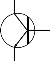
Transistors
The diode is the simplest semiconductor device, made up of a p-type semiconductor and an n-type semiconductor in contact. It can conduct in only one direction, but it cannot control the size of an electric current. Transistors are more complicated electronic components which can control the size of the electric current flowing through them.
A small current can be used to turn the transistor on and off. The transistor then controls a more complicated or powerful current through other components. When a transistor is used in this way it is said to be in switching mode as it is acting as a remotely controlled switch. Switching circuits can be used in a computer to process and store digital information. A computer would not work without the millions (or billions) of transistors in it.
The transistor is considered by many to be one of the greatest discoveries or inventions in modern history. Key to the importance of the transistor in modern society is its ability to be produced in huge numbers using simple techniques, resulting in their low cost. Computer ‘chips’ consist of millions of transistors. The low cost has meant that the transistor has become an almost universal tool for non-mechanical tasks. Whereas a common appliance, say a refrigerator, would have used a mechanical device for control, today it is often less expensive to simply use a few million transistors and the appropriate computer program to carry out the same task. Today transistors have replaced almost all electromechanical devices, most simple feedback systems, and appear in huge numbers in everything from computers to cars.
The operational amplifier
The operational amplifier is a special kind of electronic component which is made from transistors and is used to change voltage. Operational amplifiers are usually called op-amps for short. They are used extensively in all kinds of audio equipment (amplifiers, mixers, etc.) and in instrumentation. They also have many other uses in other circuits, for example comparing voltages from sensors.
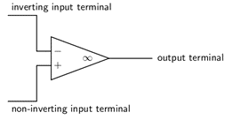
The operational amplifier has two input terminals and one output terminal. The voltage of the output terminal is proportional to the difference in voltage between the two input terminals. The output terminal is on the right (at the sharp point of the triangle). The two input terminals are drawn on the left. One input terminal (labelled with a + on diagrams) is called the non-inverting input. The other input terminal (labelled -) is called the inverting input. The labels + and – have nothing to do with the way in which the operational amplifier is connected to the power supply. Operational amplifiers must be connected to the power supply, but this is taken for granted when circuit diagrams are drawn, and these connections are not shown on circuit diagrams. Usually, when drawing electronic circuits, ‘0V’ is taken to mean the negative terminal of the power supply. This is not the case with op-amps. For an op-amp, ‘0V’ refers to the voltage midway between the + and – of the supply.
Exercise 3.2
- What is a diode?
- What is a diode made of?
- What is the term which means that a diode is connected the ‘wrong way’ and little current is flowing?
- What is an LED?
- List five applications of LEDs.
- What are transistors used for?
- What are operational amplifiers used for?
The full solutions are at the end of the unit.
Summary
In this unit you have learnt the following:
- A logic gate is an electronic device that creates logical decisions depending on the various combinations of digital signals accessible on its inputs (sensors).
- The functioning of a logic gate is in a truth table which displays all possible combination of the inputs and corresponding output value.
- Logic gates are used in computers, push button switches, controlling streetlights, data transfer, burglar alarms and buzzers.
- Active circuit components respond to changes in voltage and current. They include diodes, light emitting diodes, transistors, and operational amplifiers.
- A diode is an electronic device that allows current to flow in one direction only.
- Diodes are used to convert AC power to DC power, to remove the negative component of an AC signal, to protect sensitive electronic components and to make sure current only flows in the proper direction.
- A light-emitting diode (LED) is a diode device that emits light when charge flows in the correct direction through it.
- LEDs are used for signs, status indicators, remote controls, traffic lights, lighting, and movement sensors.
- Transistors are electronic components which can control the size of the electric current flowing through them.
- Transistors act as remote-controlled switches.
- The operational amplifier is an electronic component which is made from transistors and is used to change voltage.
- Operational amplifiers are used extensively in audio equipment (amplifiers, mixers etc.) and in instrumentation.
Unit 3: Assessment
Suggested time to complete: 30 minutes
- Write the number of the correct description for the logic gate next to the letter of its name:
Logic gate Description - NAND
- The output is ‘high’ if either of the inputs is ‘high’. The output is ‘low’ if both the inputs are ‘high’ or if both the inputs are ‘low’.
- NOT
- The output is ‘high’ if both the inputs are ‘high’, and the output is ‘low’ if both or either of the inputs is ‘low’.
- OR
- The output is ‘high’ if both the inputs are ‘high’ or if both the inputs are ‘low’. The output is ‘low’ if either of the input is ‘low’.
- AND
- The output is ‘high’ if both the inputs are ‘low’ and if either of the inputs is ‘low’. The output is ‘low’ if both the inputs are ‘high’.
- XOR
- The output is ‘high’ if both the inputs are ‘low’. The output is ‘low’ if both the inputs are ‘high’ or either of the inputs is ‘high’.
- XNOR
- The output is ‘high’ if both the inputs are ‘high’ or one of the inputs is ‘high’. The output is ‘low’ if both the inputs are ‘low’.
- NOR
- The output is ‘high’ if the input is ‘low’ and vice versa.
- State the difference between passive and active circuit components.
- Tabulate the active circuit elements you have learnt under the headings: name, symbol, use.
- Which of the light bulbs in the circuits below will light up? Explain.
- A LED is a diode that emits light, and for these special types of diodes there are many applications. The digital number display on Izaan’s calculator is produced by a system of LEDs. The circuit diagram for the LEDs for a single number 8 is given beneath.
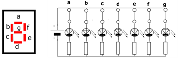
- What switches must be opened to change this to a number 2?
- What number would be seen if all switches were closed but LED “c” is connected in reverse? Explain briefly.
The full solutions are at the end of the unit.
Unit 3: Solutions
Exercise 3.1
- A logic gate is an electronic device that creates logical decisions depending on the various combinations of digital signals accessible on its inputs.
- There are seven types of logic gates. They are:
- NOT gate (inverter)
- AND gate (multiplication)
- OR gate (addition)
- NAND gate
- NOR gate
- XOR gate
- XNOR gate.
- Logic gates are used in computers, push button switches, controlling streetlights, data transfer, burglar alarms and buzzers.
Exercise 3.2
- A diode is an electronic device that allows current to flow in one direction only.
- Diodes consist of a p-type and an n-type semiconductor in a p-n junction.
- Reverse biased.
- Light emitting diode.
- signs
status indicators
remote controls
traffic lights
lighting
movement sensors. - Transistors are used as remote-controlled switches.
- Operational amplifiers are used in audio equipment such as amplifiers and mixers, and in instrumentation.
Unit 3: Assessment
- .
- 4
- 7
- 6
- 2
- 1
- 3
- 5
- Passive components do not change their behaviour and therefore always have the same response to changes in voltage or current. Active components respond to changes in voltage and current.
- Table:
Name Circuit symbol Uses Diode 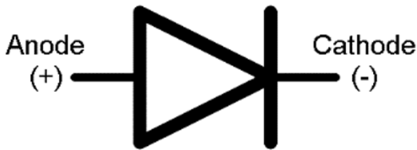
- to convert AC power to DC power
- to remove the negative component of an AC signal
- to protect sensitive electronic components
- to make sure current only flows in the proper direction.
LED 
- signs
- status indicators
- remote controls
- traffic lights
- lighting
- movement sensors
Transistor 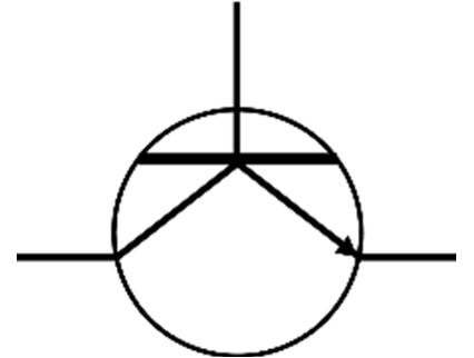
- remote-controlled switches
Operational amplifier 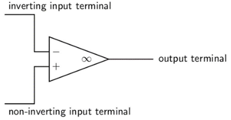
- audio equipment
- amplifiers
- mixers
- instrumentation
- B1 – the diode is connected in the forward biased direction, the cathode (positive) is connected to the positive terminal of the battery and the anode (negative) is connected to the negative terminal of the battery.
- .
- Switches b) and e)
- 9
Media Attributions
- img01_Figure1 © L Kleynhans is licensed under a CC BY (Attribution) license
- img02_Figure2 © L Kleynhans is licensed under a CC BY (Attribution) license
- img03_Figure3 © L Kleynhans is licensed under a CC BY (Attribution) license
- img04_Figure4 © L Kleynhans is licensed under a CC BY (Attribution) license
- img05_Figure5 © L Kleynhans is licensed under a CC BY (Attribution) license
- img06_Fiigure6 © L Kleynhans is licensed under a CC BY (Attribution) license
- img07_Figure7 © L Kleynhans is licensed under a CC BY (Attribution) license
- img08_Figure8 © L Kleynhans is licensed under a CC BY (Attribution) license
- img09_Figure9 © L Kleynhans is licensed under a CC BY (Attribution) license
- img10_Figure10 © OpenStax is licensed under a CC BY (Attribution) license
- img11_Figure11 © OpenStax is licensed under a CC BY (Attribution) license
- img12_Figure12 © OpenStax is licensed under a CC BY (Attribution) license
- img13_Figure13 © OpenStax is licensed under a CC BY (Attribution) license
- img14_figure14 © OpenStax is licensed under a CC BY (Attribution) license
- img15_AssessmentQ4 © OpenStax is licensed under a CC BY (Attribution) license
- img16_AssessmentQ5 © OpenStax is licensed under a CC BY (Attribution) license
- img17_AssessmentQ3answer © OpenStax is licensed under a CC BY (Attribution) license
- img17_AssessmentQ3answer © OpenStax is licensed under a CC BY (Attribution) license
- img17_AssessmentQ3answer © OpenStax is licensed under a CC BY (Attribution) license
- img17_AssessmentQ3answer © OpenStax
systems that use signals to represent data as a sequence of discrete values
alternating current; current only flows in one direction
direct current; current changes direction in regular time intervals
the entire distribution of electromagnetic radiation according to frequency or wavelength
liquid crystal displays
consisting of letters and numbers
emitting light as a result of being heated
producing light when electricity flows through a tube of gas
light of only one colour
